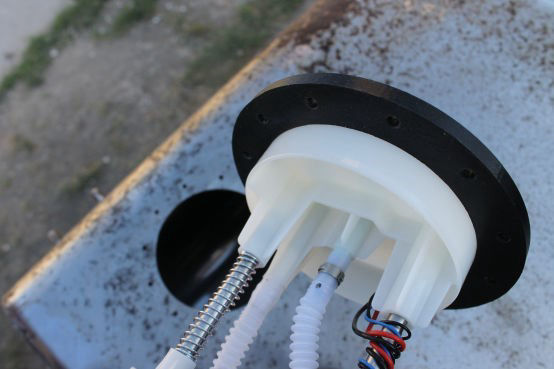
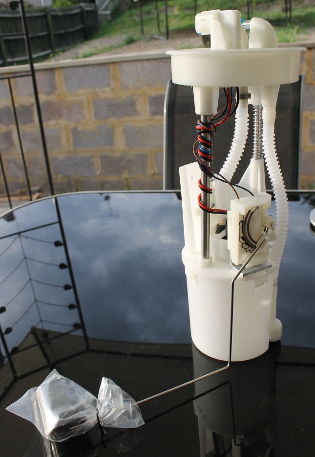
The Pump

Fuel Pump P/N: ESR 3926Tank depth range: 255mm to 295mm
Fitted to: Discovery Series 1 V8
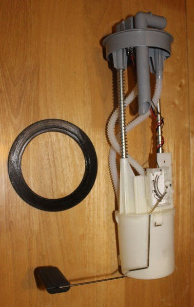
During the quest for an in-tank electric high pressure fuel pump for my Scimitar I discovered that Land Rover used a nice self contained unit complete with sender on a range of their vehicles that can be found in the aftermarket world for extremely reasonable prices. A benefit of these units is that they are mounted on sprung shafts and so have a certain amount of automatic built in depth/height adjustment.
There is nothing special about the Scimitars fuel tank so this guide should be suitable for most applications.
Your tank will need a flat mounting surface on the top of at least 150mm (6") diameter at the position you want to fit it. This should of course be directly over the lowest part of the fuel tank.
The tools mentioned above are in addition to your standard tool kit of course.
You will also need to ensure that your fuel tank has not only be drained and flushed but has been extremely well ventilated to ensure that no trace of fuel vapour remains in any seams. My tank had been dry for over a year before I started this.
Mounting Collar
Other than the differences in length and the addition of the breather connection on the Range Rover P38 sourced pump, both units are identical.
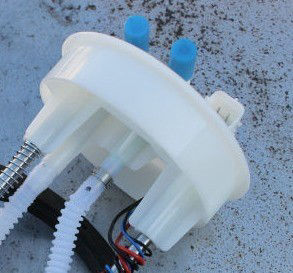
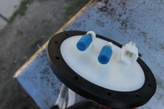
On original fitment they sat in a mounting collar moulded into the original plastic fuel tank with a large retaining ring screwed down over the top. There is a 4mm wide lip running around the top of the top cap to facilitate this.
The 4mm lip doesn't give much margin for error and is insufficient to enable a good seal. Therefore an adapter ring is required.
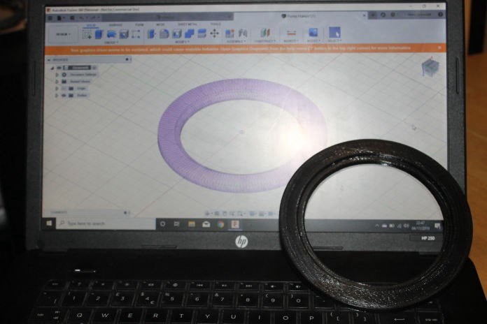
If you have access to a machine shop you could make one on a lathe.
Alternately you can do what I did and have one 3D printed.There are plenty of online service available and I will happily send you the file if you email me.
It needs to be printed 100% solid as you will be drilling mounting bolts holes through it later.
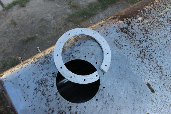
The ring has a 150mm external diameter, 110mm internal diameter and is 7mm thick.
The internal diameter is increased to 120mm diameter of a depth of 2mm on one face to accommodate the lip.
Please pay careful attention; this work needs to be carried out in the order shown.
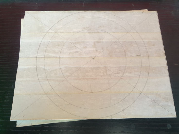
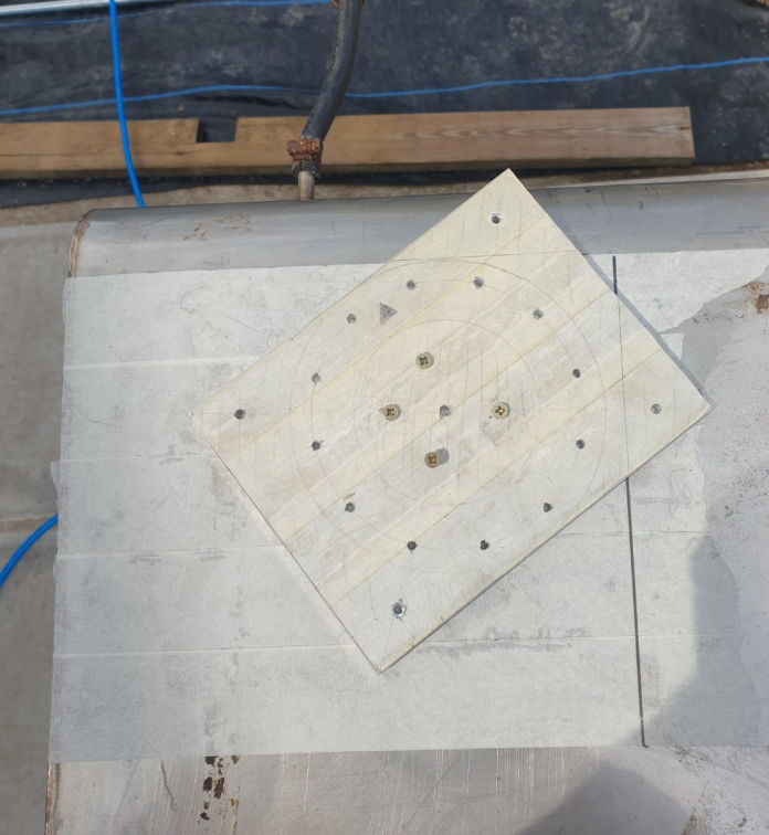
Cover one face of the alloy plate with masking tape.
Cut the alloy plate in half to give two matching squares.
Find and mark the centre of one of the plates.
From this point draw:
150mm dia circle - This is the external diameter.
130mm dia circle - This is for the mounting bolts.
90mm dia circle - This is the top clamping plate clearance hole.
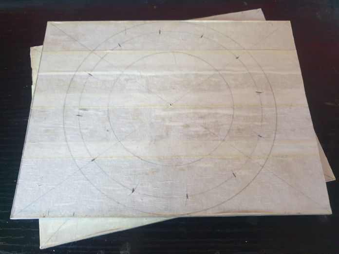
The 130mm dia bolt hole circle needs 12 equally spaced marks around its circumference for the bolt hole positions.
Shade the area outside the 150mm dia circle.
Shade the area inside the 90mm dia circle.
These are the 'waste material' areas.
Draw a small triangle within the resultant ring between two of the bolt hole positions. This is your alignment mark.
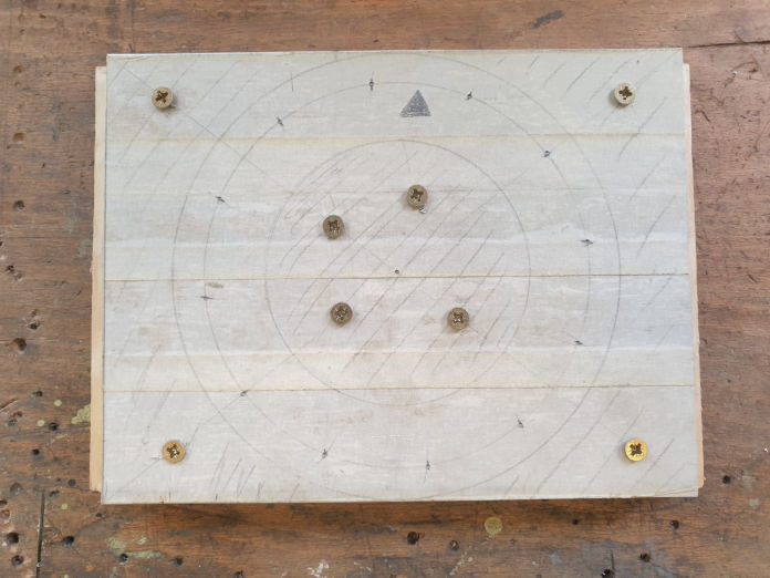
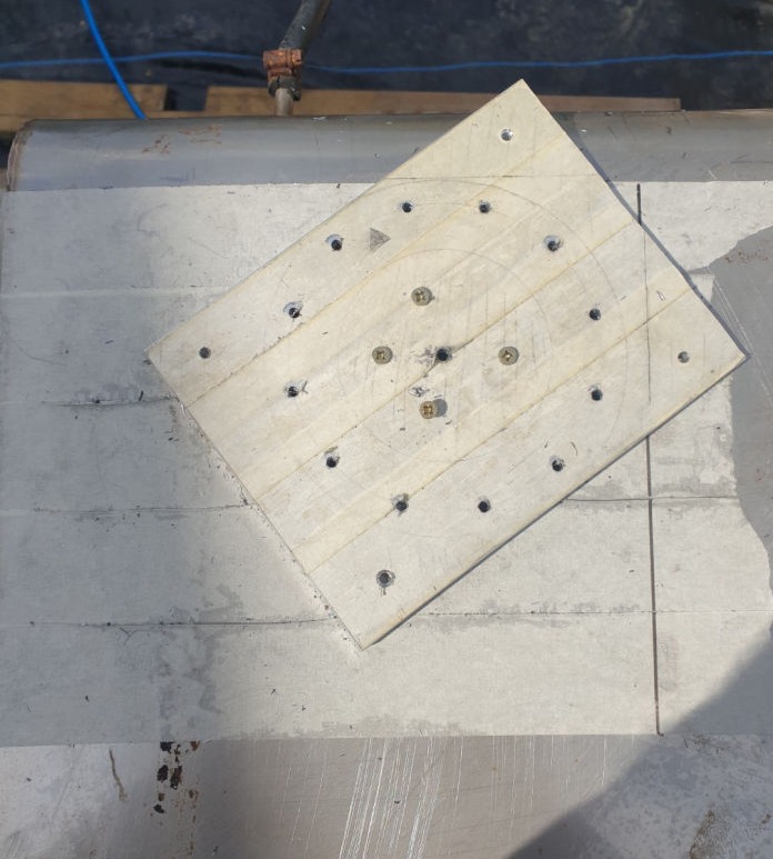
Place this plate on top of the other (both plates masking tape face up) and place them both on a piece of scrap wood of at least the same size.
Drill a hole through both plates in each corner in the outer waste material area and secure the stacked plates to the scrap wood with self tapping screws.
Drill four holes through both plates in the inner waste material area and secure with self tapping screws. It is best not to make these inner screw holes uniformly spaced so that the two plates only align in one position.
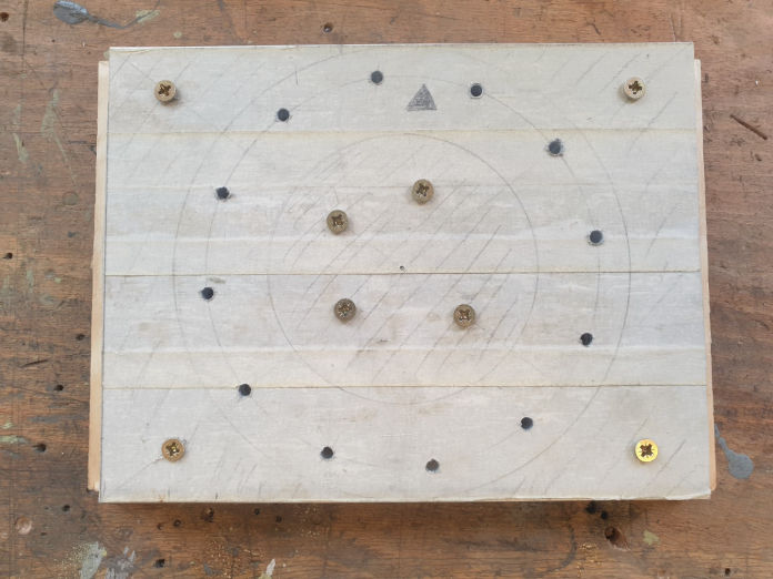
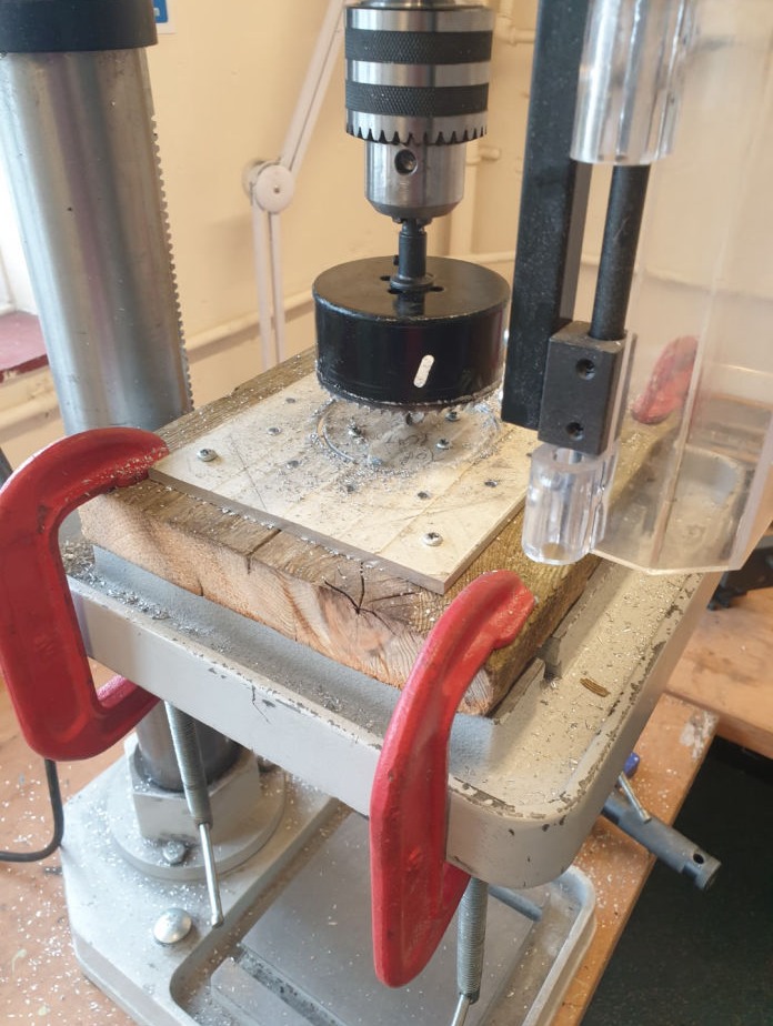
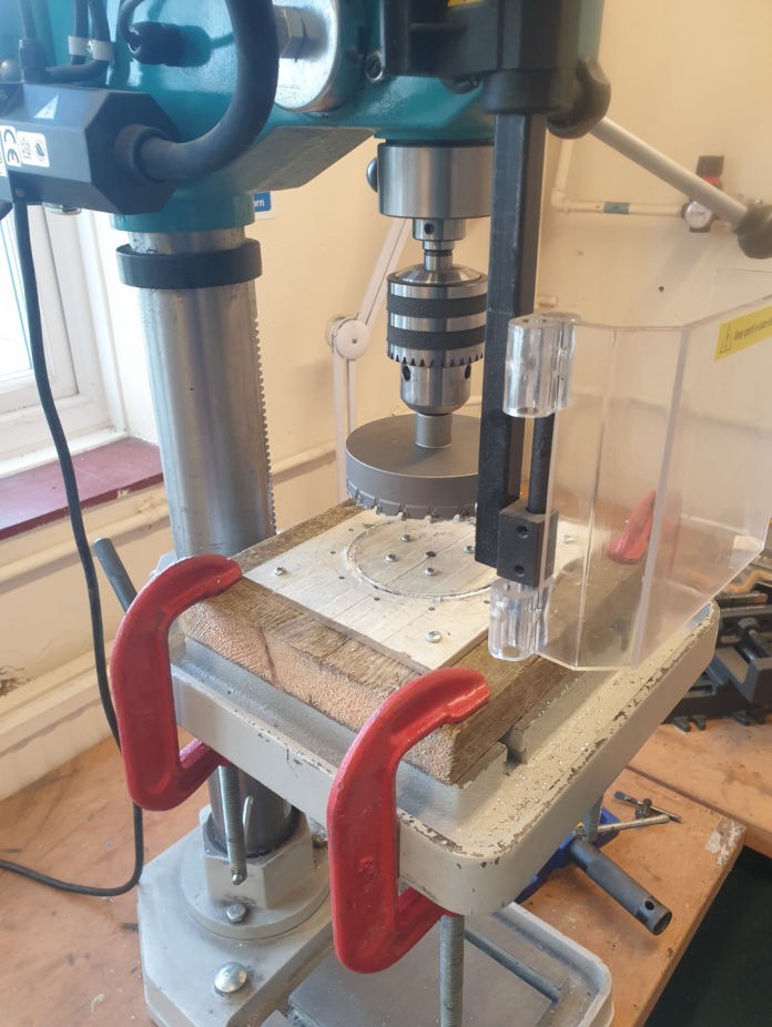
Now that the two plates are locked together work can start on fabricating the clamping rings themselves. A pillar drill would be advantageous.
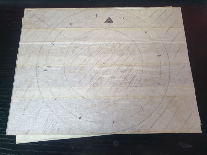
Check the diameter of the pilot drill in your hole saws and drill a hole through the centre of the plates to the same diameter. If the pilot drills are of different diameters then drill to the smallest one (hole not yet drilled in the photo).
Careful! Drill the pre-marked ring of bolt holes but to the diameter hole required for the tap! M5 = 4.2mm dia 10unf = 5/32" (3.9mm) dia
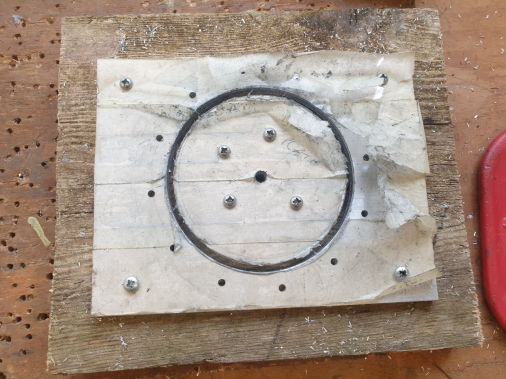
Unmount the two plates from the wood and carefully separate without disturbing their orientation.
Copy the alignment mark made earlier to the lower plate between the same bolt holes. This will ensure that any variance in the positioning of the ring of bolt holes is accounted for.
Draw the 150mm dia circle onto the lower plate (which is the upper one in the photo still on the piece of wood. Sorry).
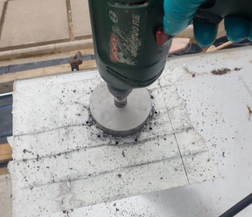
This next bit involves using an electric powered, spark and heat inducing piece of equipment on a container that has spent it's entire life exposed to petrol vapours. If you really need me to point out the danger of this then perhaps you shouldn't be doing this.
My tank had been empty, flushed and venting for over a year and I still filled it with water before proceeding.
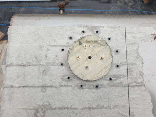
Identify where on your well ventilated tank you want to mount your pump. Take into consideration the location and swing of the level sender if you are not using the item built into the pump, or the direction of swing of the level sender on the pump if you are using it. Also look out for any obstructions to the top of the tank when the tank is mounted back in the vehicle.
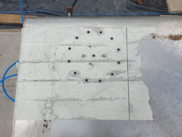
Apply masking tape to the area
Mark out any internal baffles in the tank or areas to be avoided (ignore the four small circles).
If the edge of the tank is curved like mine, lay a flat edge along it and mark where it starts to curve. You need to ensure you allow for the internal clamping ring to sit flush against the flat surface when positioning.
Place the top plate in position with the alignment mark lined up to a reference point on your tank (filler neck, corner etc...)
Mark through the inner waste material screw holes onto the top of the tank.
Remove the top plate and drill these four holes to a size suitable for pilot holes for the screws you used previously to mount the plates to the scrap wood.
Assuming you survived, reposition the top plate (remember the alignment mark) and secure to the top of the tank with the four self tapping screws.
This has just become your drill guide!
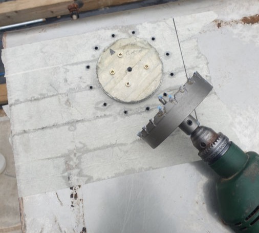
The ring of bolt holes in the top plate are currently undersize for the tap. These need to be opened up to the correct size to clear the bolts.
With the top plate secured to the tank, open up the ring of bolt holes drilling all the way through the top of the tank at the same time.
Remove the top plate from the tank and admire your handy work.
Re-secure the top plate (on its own) to the piece of scrap wood with all eight self tapping screws.
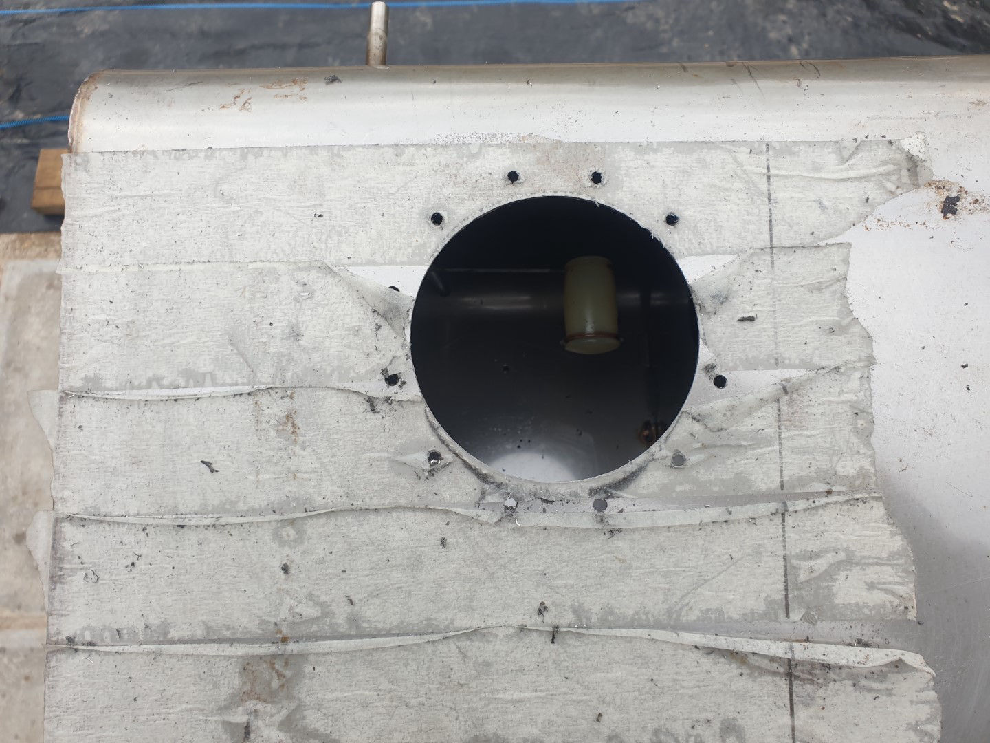
Using the 90mm hole saw cut out the large central hole. This will be heavy going so be patient, you don't want to damage the hole saw.
Once done remove from the scrap wood. The central waste material section can now be discarded.
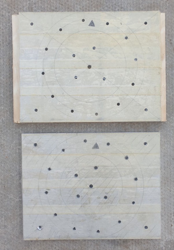
Cut around the 150mm diameter line to create a ring. A band saw would be great but a hacksaw and file will get the job done.
Write 'Top Plate' on it to avoid any mishaps, ensure that the alignment mark is still clearly visible.
Put the top clamping ring to one side.
Re-secure the lower plate (on its own) to the piece of scrap wood with all eight self tapping screws.
Extend the alignment mark to the inner wast material area.
Using the 110mm hole saw cut out the large central hole. This will be heavy going so be patient, you don't want to damage the hole saw or oversize the hole.
Remove the lower plate from the scrap wood and cut around the 150mm dia circle line as before to create a ring.
Tap the clamping bolt holes.
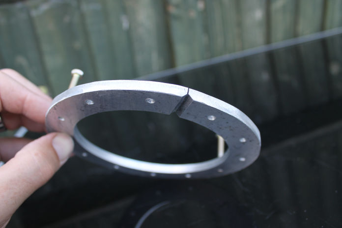
Cut through the ring at the alignment mark, directly between the two bolt holes.
Chamfer the cut edge as shown on the lower surface of the ring (non-masking tape side), this will aid insertion into the tank later.
Hold the two clamping rings against each other in their correct orientations with alignment mark and cut slot lined up.
With a file, make a permanent mark on the edge of the top clamping ring in line with the slot of the lower clamping ring.
Extend the mark part way over the top face. This will not only give you a reference for orientation, but will also indicate which side is the top face.
Remove the masking tape and carry out any necessary deburring.
That is the top clamping ring complete.
Returning to the lower clamping ring, mark out, drill and tap four more equally spaced bolt holes along the 130mm dia line mid-way between the clamping bolt holes. These are for the countersunk screws.
Remove the masking tape and carry out any necessary deburring.
That is the lower clamping ring complete.
Mounting Collar
Clamp the top clamping ring onto the 3D printed (or machined) mounting collar with the 2mm deep recess against the bottom face of the clamping ring. Make sure that they are aligned to each other.
Using the top clamping ring as a guide, drill the 12 clamping bolt holes through the mounting collar.
Whilst still clamped together, using a file, extend the alignment mark on the edge of the top clamping ring onto the mounting collar.
Detach the top clamping ring from the mounting collar and clamp the lower clamping ring in place, clamping ring top face against mounting collar bottom (flush) face. Ensure that the split in the mounting ring is lined up with the new alignment mark on the mounting collar.
Carefully mark through the positions of the four additional holes onto the mounting collar.
Detach the lower clamping ring and drill four clearance holes at these locations.
From the top (recessed) face of the mounting collar, countersink these four additional holes to suite the countersunk screws.
That is the mounting collar complete.
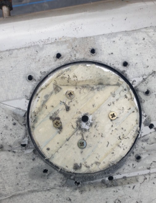
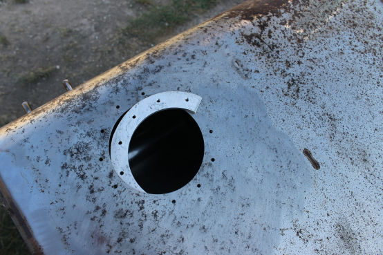
Locate the mounting collar onto the tank ensuring that the alignment mark is lined up with whatever tank reference you used and that the central hole and all 12 clamping bolt holes line up.
Mark the positions of the four countersunk screws onto the tank.
Remove the mounting collar and drill four clearance holes for the countersunk screws.
Remove the masking tape from the tank, de-burr the tank as necessary and clean out any debris.
Finally, make three sealing gaskets using the lower clamping ring as a pattern.
Test Assembly
You should now have a kit of parts

The top plate of the pump assembly should want to sit a bit proud of the mounting collar so that when pushed fully home the springs provide some tension to push the pump unit against the lower tank skin.
Position the top clamping ring, paying attention to the alignment mark. Check all the bolt holes line up and fit all of the bolts but do not tighten.
Check that you are happy with the fit, the positioning of the pipe connections and that the level sensor has full and free movement.
Once happy, remove the pump, mounting collar and clamping rings.
Re-locating the Level Sender Unit
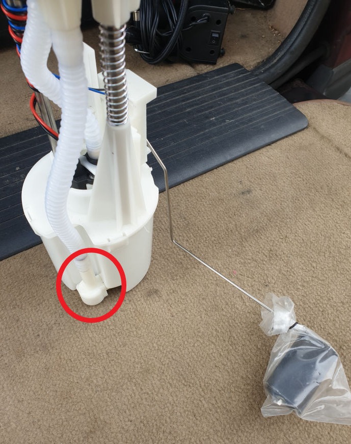
Depending on your application it may be desirable to relocate the level sender. It was in my case as my tank is tapered so having the fuel pick-up for the pump chamber at the lowest point would have had the fuel level sender float poking through the front wall of the tank. Fortunately the level sender is detachable and there is space to remount it on the other side of the pump chamber.
The level sender is a separate unit secured to the pump chamber by a self tapping screw.
There is space on the other side of the pump chamber to mount it on a new bracket.
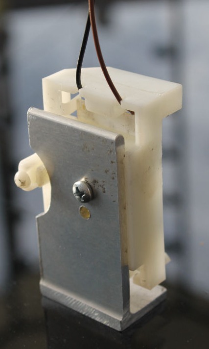
The new bracket is cut from extruded alloy 'L' section (or 'T' section with one edge cut off in my case). Folded sheet metal is likely to flex under the weight of the moving fuel (cornering etc...)
This is bolted through the top of the pump chamber with metal spreader plates fitted inside to spread the load. The pump chamber body simply unclips from it's top plate.
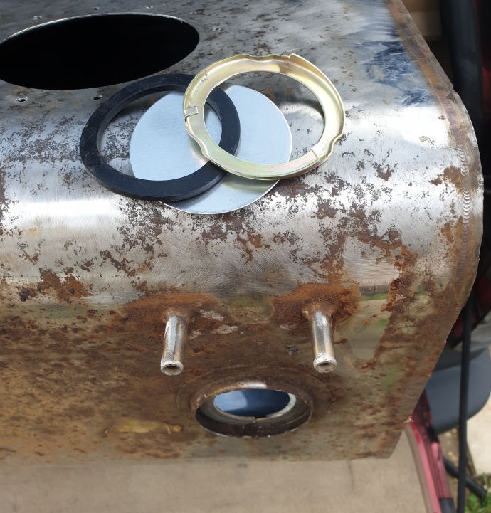
The original sender hole is then blanked off with a disc of metal using new original style seal and retaining ring.


Made with
Landing Page Software